Easy Guide to Soldering Wire to Circuit Board
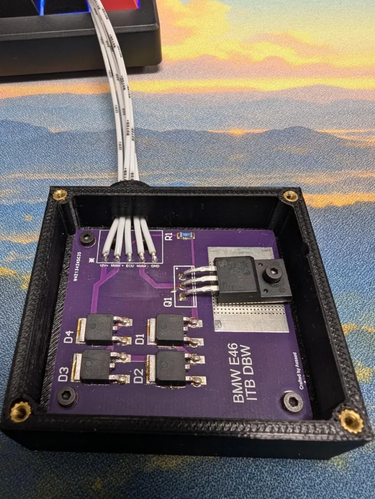
Soldering an electric wire to a circuit board can be a straightforward task if you follow these steps carefully. Here’s a step-by-step guide to help you through the process:
Tools and Materials Needed:
- Soldering iron (with a fine tip)
- Solder (preferably rosin-core solder)
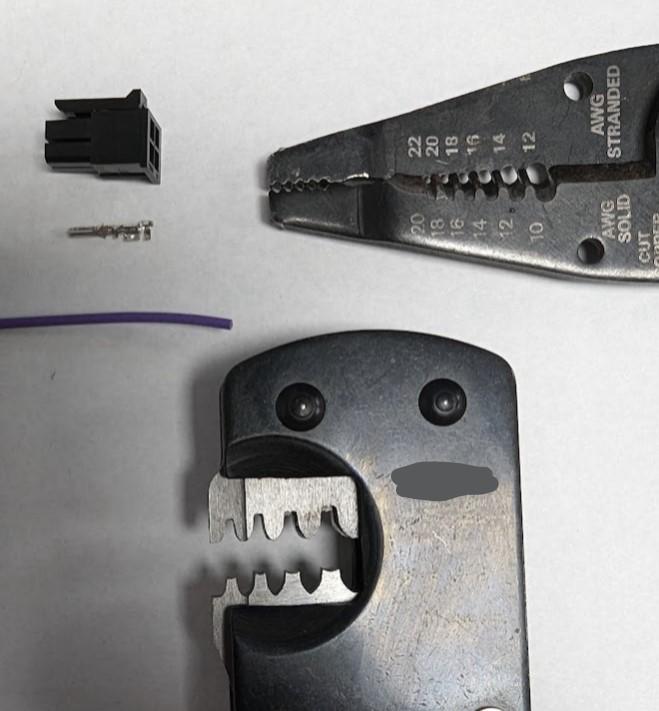
- Wire strippers
- Heat-resistant mat or surface
- Tweezers (optional)
- Safety glasses
- Cleaning sponge or brass sponge for the soldering iron tip
- Flux (optional, but recommended for better connections)
- Wire cutters (flush cutters)
Step-by-Step Guide:
- Prepare the Workspace:
- Set up a clean, well-lit work area. Use a heat-resistant mat to protect your surface and ensure good ventilation.
- Gather Components:
- Have your circuit board, electric wire, soldering iron, solder, and any additional tools ready.
- Strip the Wire:
- Use wire strippers to remove about 1/4 inch (6 mm) of insulation from the end of the wire. Be careful not to nick the copper wire.
- Tin the Wire (Optional):
- Heat the soldering iron and apply a small amount of solder to the tip. This helps with heat transfer.
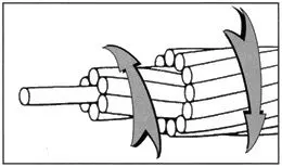
- Hold the stripped wire with tweezers and touch the soldering iron to the exposed copper. Feed solder onto the wire until it is coated. Remove the heat and let it cool.
- Prepare the Circuit Board:
- Identify the hole or pad on the circuit board where you will solder the wire. If necessary, clean the area with isopropyl alcohol to remove any contaminants.
6.Clean Solder Iron Tip:
- Before soldering its good practice to clean the tip of the iron of any contaminates. Either with the brass sponge or wet sponge, remove any excess material on the tip of the soldering iron. The tip should come out looking polished.
- Insert the Wire:
- Pass the tinned end of the wire through the hole or lay it on the pad where it will be soldered.
- Heat the Connection:
- Place the tip of the soldering iron on the wire and the circuit board pad simultaneously. This allows both surfaces to heat up.
- Apply Solder:
- After a second or two of heating, feed solder into the joint (not directly onto the soldering iron). The solder should flow around the wire and pad. Remove the solder and then the soldering iron after a second or two. To allow a proper solder joint, too soon could leave the solder “cold”.
- Allow to Cool:
- Hold the wire steady for a few seconds to allow the solder to cool and form a solid connection. Do not move the wire during this time.
- Inspect the Joint:
- Check the solder joint for a smooth, shiny appearance. It should look like a small, conical mound. If it appears dull or has cracks, you may need to reheat and add more solder.
- Trim Excess Wire (if necessary):
- If there’s excess wire sticking out, use wire cutters to trim it to a suitable length, ensuring not to cut too close to the solder joint.
- Clean the Area:
- If there is an excess amount of flux, clean the area again with isopropyl alcohol to prevent corrosion.
- Test the Connection:
- Finally, if applicable, reassemble the circuit and test to ensure the connection is working properly.
Safety Tips:
- Always wear safety glasses to protect your eyes from solder splashes.
- Be cautious of the hot soldering iron and molten solder to avoid burns.
- Work in a well-ventilated area to avoid inhaling fumes.
By following these steps, you should be able to successfully solder an electric wire to a circuit board. Happy soldering!


