Soldering holds a close place to my heart. Weird thing to say but it’s true. I learned in my electronics class in high school (shout out Mr. Faddis). In one way or another I carried this skill until today. Really this class inspired me to become an electrical engineer and now I’m here working in wire.
Even though it’s a relatively simple thing to do, there are a lot of nuances that can lead to a good solder joint or bad one. Let’s see if we can write a comprehensive article that will cover what to look out for and how to set up your iron (and yourself) for success.
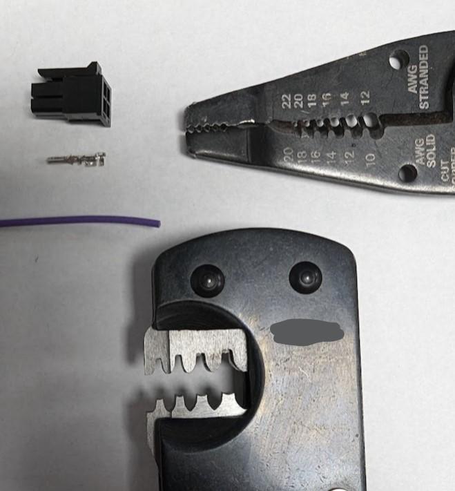
I’ve used all different levels of solder irons, from cheap Amazon to Hakko solder irons. Obviously, the accuracy and consistency of the Hakko is where they made their name, but any entry level soldering iron will suffice when you are starting out. Something overlooked is the tips, there are a variety of shapes and sizes depending on the job at hand and how much area you are looking to heat. For PCBs you’d want something narrower, for wire-to-wire a wider tip is ideal.
The objective of soldering is bonding two metals together with a third alloy with a low melting point. Whether it is two wires or pin to pad on a PCB you will need to heat both metals at the same time then apply the solder. It is good to hold the solder against the joint for a second or two after applying the solder. If you pull the iron away too quickly it could result in a cold solder joint. Which is more prone to failure under stress. What you want to do is apply the solder to the two metals and hold it there for a second to allow the solder to full flow through the strands or PCB. There are a lot of visual indicators that a solid solder joint has been made. For instance, in stranded wire I like to see all the strands covered in solder. Not fully covered, just captured in the solder.
In a PCB, the solder joint should not look like a ball. That means the heat did not fully allow the solder to flow. You want it to look like a rounded conical shape, almost like a Hersey Kiss. If it’s possible to inspect the bottom side of the board to make sure the solder had flowed to the bottom of the board fully encompassing the pin.
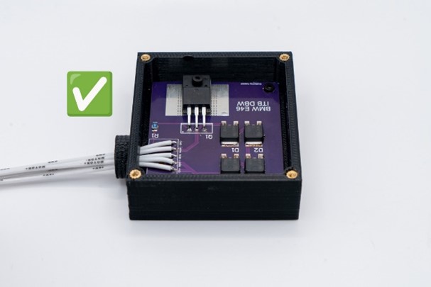
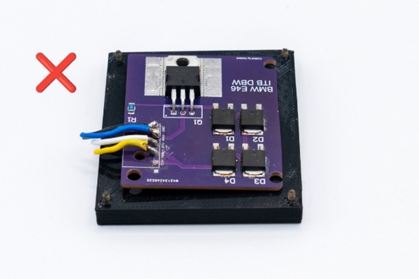
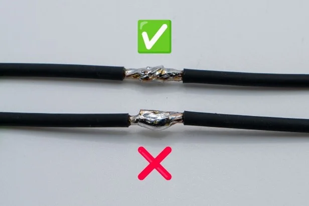
In these images, the left-hand image the solder joints for both the wire and the pins have good, controlled amount of solder, leaving ideal solder joint. The right image has too much solder on the wires, not enough heat or flow allowed the solder to fully penetrate the wire and PCB making a week joint. You can see there was a failure. Also, you can see the pins on Q1 do not have solder flowing through the pinhole. This could lead to issues in the future.
If you see a tail where the solder iron was lifted, this is likely due to a dirty iron with residue solder on the tip. It will not harm the solder joint; you can snip off the tail or clean the tip and reapply a tiny amount of solder. Overall, the color of the solder is a good indication of a solid joint. If it is a dull grey color, it’s likely a cold solder joint. What you are looking for is a shiny polished silver color.